Charge and electric field
It is known that atoms are made up of electrons, protons and neutrons. The electrons and protons are attracted to each other but are repelled with particles belonging to same category. This property can be explained with the concept off “charge”. The particles with more electrons than protons possess negative charge and those with more protons are positively charged.
Unit of charge:
The unit of charge is coulomb. Coulomb is the charge transported by a current of 1A in a time of 1 second.
The magnitude of charge possessed by an electron or proton is 1.6 × 10⁻¹⁹C.
Electric forces:
The magnitude of force acting on two charged objects (q1 and q2) is proportional to the product of charges and inversely proportional to square of distance (r) between them.
𝐹 = (1/4𝜋𝜖0)(𝑞1𝑞2/𝑟2)
This force is attractive if the objects are of opposite charge and repulsive if the objects are of same charge.
𝜖0 is the permittivity of free space. It has a value of 8.854 × 10⁻¹²𝐶2𝑁−1𝑚−2.
If the medium between the objects is not vacuum, then permittivity of corresponding medium should be used.
E.g.: Two charges +10nC and -10nC are separated by a distance of 15mm.
a) Calculate the force acting between the charges.
b) Determine whether this force can lift a small piece of paper of area 2mm
Answer.
a) The force acting between them is 𝐹 =((−10−8 × 10⁸)/4𝜋𝜖0(15 × 10−3)2 = 4 × 10⁻³N
b) The piece of paper has a mass of 1.3 × 10⁻⁷𝑘g about and weight of 1.3 × 10⁻⁶N. So, this force is sufficient to lift the piece if paper.
Electric field:
The electric field strength of a charge is the force exerted by the charge on a unit charge.
The electric field strength of a charge Q at a distance r from it is
𝐹 = (1/4𝜋𝜖0)(Q/𝑟2)
Electric field lines:
Electric field lines represent the direction of forces in an electric field.
Given below are few rules to be followed while drawing field lines:
- The lines start at positive charges and end at negative charges.
- When the field is strong, the lines are close.
- The lines do not cross each other.
- The lines meet a conducting surface at 90˚.
- The lines emerge radially out of a positive point charge.
The electric field is a vector and the resultant field due to two charges is the vectoral sum of two fields due to charges at that point.
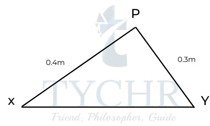
E.g.: Two point charges, a +25nC charge X and a +15nC charge Y are separated by a distance 0.5m.
a) Calculate the field at the midpoint of charges.
b) Calculate the distance from X at which the field is zero.
c) Calculate the magnitude of field at point P.
Answer.
a) The field due to X is 𝐹 = (1/4𝜋𝜖0)(25 × 10−9/(0.25)2) = 3600𝑁𝐶−1
The field due to Y is
𝐹 = (1/4𝜋𝜖0)(15 × 10−9/(0.25)2) = 2200𝑁𝐶-1
The field strength acts in opposite direction.
So, the resultant field is 3600-2200=1400NC-1 towards Y.
b) For the field to be zero,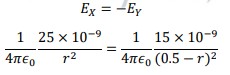 r=0.28m
c) At P,
𝐹 = (1/4𝜋𝜖0)(25 × 10−9/(0.4)2) = 1400𝑁𝐶-1
𝐹 = (1/4𝜋𝜖0)(15 × 10−9/(0.3)2) = 1500𝑁𝐶-1
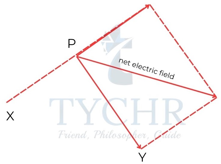
The magnitude of resultant field = √(14002 + 15002 = 2100𝑁𝐶-1
Electric potential:
Electric potential is the work done on a unit charge to move it from a point of zero reference (infinity) to the point of concern.
For a point charge q, the potential at a distance r is
V = (1/4𝜋𝜖0)(q/r)
The electric field at a point is the negative of change in potential for a small change in distance.
𝐸 = −(Δ𝑉/Δ𝑥)
Equipotential lines:
Equipotential lines are lines connecting the points of equal potential. The field lines are perpendicular to equipotential lines.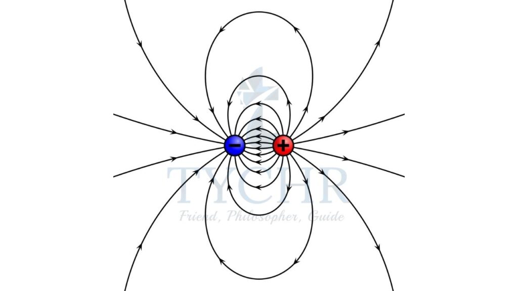
Equipotential and field lines:
Point charge: The field lines are radially outward and the equipotential lines are concentric circles around the charge.
Charged spheres: The field and potential outside the sphere is the same as that of a point charge placed at the centre of the sphere. If the sphere is conducting, the total charge is concentrated on the surface of the sphere. The potential inside this sphere is same as that at a point just outside the sphere and the field is zero.
Coaxial conductors: Equipotential lines are concentric circles to the axis of cable and field lines are radially outward.
Point charge and a charged plate: The field lines are radial to the point charge and are perpendicular to the plate.
Near a charged plate: For a charged plate of surface charge , the field near the plate far from edges is 𝜎/2𝜖0 and is perpendicular to the plate. This does not apply near edges due to the edge effects.
Moving charge
Electric current:
When a charge moves it results in an electric current. When an object allows electric current to pass through it, the object is said to conduct electricity.
Conduction:
Metals: In metals, the free electrons are charge carriers. The electric current is due to the movement of electrons.
Liquids and gases: In few liquids and gases, the presence of free ions allows for the conduction of electricity. In case of strong electric fields, the atoms in a non-conducting field breakdown to form ions and they conduct electricity. This is called electrical breakdown.
The electric current passing through a conductor is given by
𝑒𝑙𝑒𝑐𝑡𝑟𝑖𝑐 𝑐𝑢𝑟𝑟𝑒𝑛𝑡 𝐼 =𝑡𝑜𝑡𝑎𝑙 𝑐ℎ𝑎𝑟𝑔𝑒 𝑝𝑎𝑠𝑠𝑒𝑑 𝑡ℎ𝑟𝑜𝑢𝑔ℎ 𝑎 𝑝𝑜𝑖𝑛𝑡/𝑡𝑜𝑡𝑎𝑙 𝑡𝑖𝑚𝑒 𝑡𝑎𝑘𝑒𝑛 = ∆𝑄 / ∆V
E.g.: In a shuttling ball experiment, the ball moves between two plates at a frequency of 0.67Hz and carries a charge 72nC.
a) Calculate the average current in the circuit.
b) the number of electrons transferred each time the ball touches one of the plates.
Answer.
a) The time between the ball being at the same plate = 1/𝑓 = 1/0.67 = 1.5s. The time to transfer 72nC is 0.75s.
The current 𝐼 = 72×10−9/0.75 = 96𝑛𝐴.
b) The charge transferred each time is 72×10−9/1.6×10−19 = 4.5 × 10¹¹
Drift speed:
The charge carriers move at extremely slow speed when a current flows through a conductor. This is given by: 𝐼 = 𝑛𝐴𝑣𝑞
Here, I is the current through the conductor,
n is the number of charge carriers in a unit volume
A is the area of cross section and
Q is the charge carried by the charge carrier.
Potential difference (V):
Potential difference between two points is the work done to move a unit charge between two points.
Its unit is JC-1 called volt (V).
If W is the work done for Q charge, then the potential difference is 𝑊/𝑄.
E.g.: An LED bulb is lit for 2 hours. Calculate the energy transferred if the potential difference across it is 240V and the current in it is 50mA.
Answer. The charge transferred is 50 × 10−3 × 2 × 60 × 60 = 360C
Work done = 240 × 360 = 86400J
Electromotive force:
A device which generates electrical energy produces emf. Emf is analogous to potential difference.
Electric power:
The power transmitted when a current I flows across a pd V is P=VI.
E.g.: A 3V, 1.5 W lamp is connected to a 3V battery. Calculate the current in the lamp and energy transferred in 2400s.
Answer. The current in the lamp is .
The energy transferred is 𝑃𝑡 = 1.5 × 2400 = 3600J
Electronvolt (eV) is a unit of energy obtained by product of charge of electron and a volt. This value is equal to 1.6 × 10⁻¹⁹𝐽.
Heating effects of electric current
Measuring current and pd in a circuit:
Analogue meters: They have a mechanical system of a coil and a magnet. When current flows through the coil, a magnetic field is produced which interacts with the magnetic field of magnet and a pointer attached to a spring swing around and the value of current is indicated on a scale.
Digital meters: Shows the value of pd across its terminals digitally.
Ammeter: It measures the current in the circuit. It is connected in series with the circuit and ideally there is no drop in pd across it.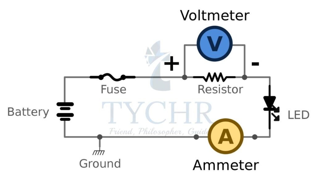
Voltmeter: It measures the pd across a component. It is connected in parallel to the component where the pd has to be measured and ideally, no current passes through it.
Resistance: Electrical resistance of a component is defined as
𝑅 =𝑝𝑜𝑡𝑒𝑛𝑡𝑖𝑎𝑙 𝑑𝑖𝑓𝑓𝑒𝑟𝑒𝑛𝑐𝑒 𝑎𝑐𝑟𝑜𝑠𝑠 𝑡ℎ𝑒 𝑐𝑜𝑚𝑝𝑜𝑛𝑒𝑛𝑡/𝑐𝑢𝑟𝑟𝑒𝑛𝑡 𝑖𝑛 𝑡ℎ𝑒 𝑐𝑜𝑚𝑝𝑜𝑛𝑒𝑛𝑡
The SI unit of resistance is ohm (Ω).
Resistivity: Resistivity is the resistance of a material of unit length of unit area of cross section. It is constant for a material at a particular temperature.
The resistance of a material is given by 𝑅 = 𝜌𝐿/𝐴
Ohm’s law:
The potential difference across a component changes linearly with current when the physical conditions of the component do not change.
This law is called Ohm’s law and materials which follow Ohm’s law are called Ohmic materials. The materials which do not follow Ohm’s law are called non-Ohmic materials.
Semi-conducting diodes:
Semi-conducting diodes are made such that it allows current flow in only one direction. Also, the current does not flow until the pd across the diode exceeds a certain value.
Thermistors:
Thermistors exhibit high sensitivity to temperature. Its resistance falls with increase in temperature and can be used to measure temperature.
Combining resistors:
For resistors in series,
The same current flows through all the resistors and the total pd is the sum of individual pds. For two resistors, this gives
𝑅𝑒𝑞 = 𝑅1 + 𝑅2
For resistors in parallel,
The pd is same for all resistors and total current is the sum of individual currents. For two resistors this gives
1/𝑅𝑒𝑞 = 1/𝑅1 + 1/𝑅2
E.g.: Three resistors are connected as shown. Find the equivalent resistance of the combination.
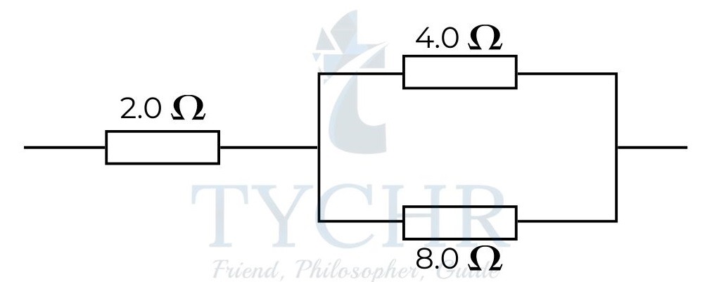
Answer. The resistors 4.0Ω and 8.0Ω are connected in parallel. The effective resistance is
1/ ((1/4) + (1/8)) = 2.67Ω
2.67 and 2.0 are connected. So, the equivalent resistance is 2 + 2.67 = 4.67Ω.
Potential dividers:
Consider the following setup.
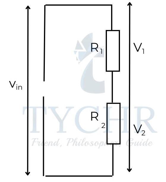
The pds across the resistors are given by:
V1= (𝑅1 /(𝑅1+𝑅2 ))𝑉𝑖n
V2= (𝑅2 /(𝑅1+ 𝑅2))𝑉𝑖n
One of the resistors can be replaced by a sensor such as a thermistor for use as a detector for temperature.
E.g.: A light sensor consists of a V battery, an 1800 resistor in series with a light dependent resistor (LDR). In dark, the pd across the resistor is 1.2V.
a) calculate the resistance of the LDR in dark.
b) When the LDR is placed in light, its resistance drops to 2400 . Find the pd across the LDR.
Answer.
a) The pd across the resistor is
𝑉𝑟 = (𝑅𝑟/(𝑅𝑟+𝑅𝐿𝐷𝑅))𝑉𝑖𝑛 = 1.2
(1800/(1800 + 𝑅𝐿𝐷𝑅)) 6 = 1.2
𝑅𝐿𝐷𝑅 = 7200Ω
b) 𝑉𝐿𝐷𝑅 = (𝑅𝐿𝐷𝑅 / (𝑅𝐿𝐷𝑅+𝑅𝑟)) 𝑉𝑖𝑛 = (2400 (2400+1800)) 6 = 2.6V
Heating effect equations:
Power dissipated by a resistor of resistance R at a pd V when a current I passes through it.
𝑃 = 𝑉𝐼 =𝑉2/𝑅= 𝐼2R
Capacitance:
A capacitor is effectively two parallel conducting plates separated by a distance. A capacitor stores opposite charge on each of the plates.
The capacitance of a capacitor storing a charge Q when pd between the plates is V is is 𝑄/V.
In terms of area of plates (A) and distance between them (d), 𝐶 = 𝜖0𝐴/d.
𝜖0 is the permittivity of free space. If the medium between the plates is not vacuum, then t should be replaced with 𝜖 = 𝜖0𝜖r. Here is the permittivity of medium and is the dielectric constant of the medium.
Combination of capacitors:
For capacitors in parallel,
The pd across the capacitors is same and the total charge on the capacitors is the sum of individual charges. This gives
𝐶𝑝𝑎𝑟𝑎𝑙𝑙𝑒𝑙 = 𝐶1 + 𝐶2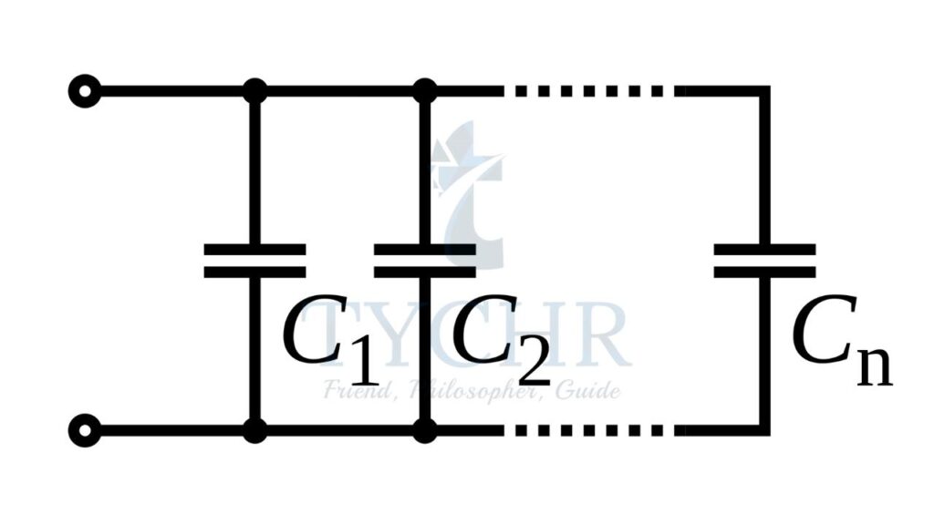
For capacitors in series,
The charge in the capacitors is same and the pd is the sum of individual pds. This gives
1/𝐶𝑠𝑒𝑟𝑖𝑒𝑠 = 1/𝐶1 + 1/𝐶2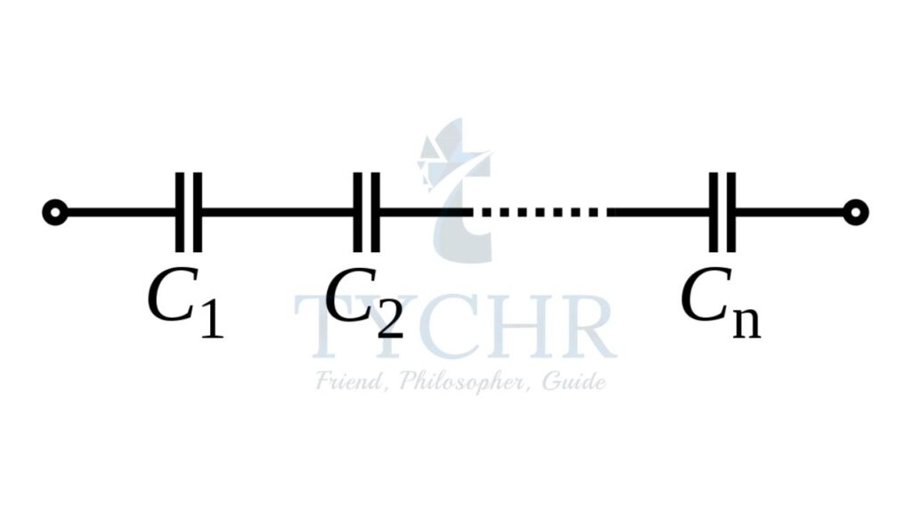
Energy stored in a capacitor:
In a capacitor, the energy is stored in the form of electric field between the plates. This energy is
𝐸 = (1/2) 𝑄𝑉 = (1/2) 𝐶𝑉2 = 𝑄2/2C
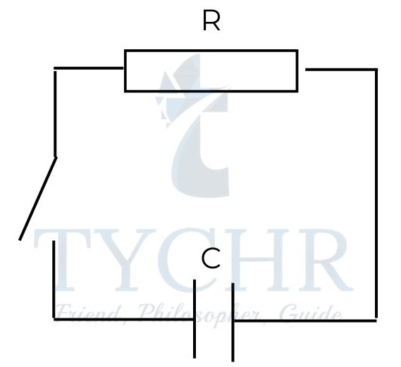
Charging and discharging of a capacitor:
Consider a circuit as shown for charging a capacitor.
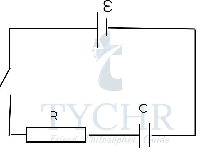
The charge on the capacitor with respect to time is given by 𝑄 = 𝐶𝑉(1 − 𝑒−𝑡/𝑅𝐶). Here RC is called the time constant and is represented by . Once the charge on capacitor reaches its maximum value (CV), the current transfer stops. Theoretically, it takes infinite time for the charge to reach its maximum value, but practically, after 3-4 time constants, the current can be assumed to be zero.
The current in the circuit during this time is given by I = (𝑉/R)(1 − 𝑒−𝑡/𝑅𝐶). The maximum value of current is V/R.
Considering the current in the circuit, find the instances at which the circuit behaves as a closed circuit where the capacitor behaves as a power source and an open circuit. |
Consider the circuit where a capacitor is discharged.
The charge on the capacitor with respect to time is given by 𝑄 = 𝑄0𝑒−𝑡/𝑅C, where 𝑄0 is the initial charge on capacitor.
The current in the circuit during this time is 𝐼 =(𝑄0/𝑅𝐶)𝑒−𝑡𝑅C.
Kirchhoff’s laws:
First law: It is a consequence of conservation of charge. It states that at any junction, the sum of incoming currents is equal to sum of outgoing currents.
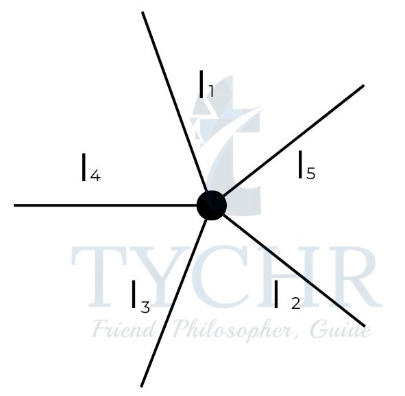
𝐼1 + 𝐼2 + 𝐼3 = 𝐼4 + 𝐼5
Second law: It is a consequence of law of conservation of energy. It states that the sum of all variations of potential in a closed loop is zero.
For a loop in a circuit, Σ𝜖 = 𝐼R
E.g.: Calculate the currents in the circuit below.
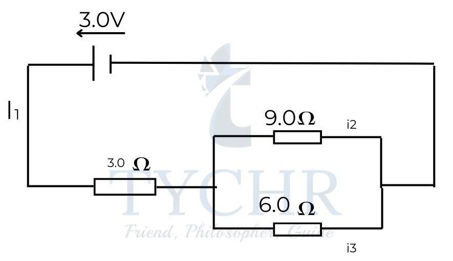
Answer. Consider the following assignment
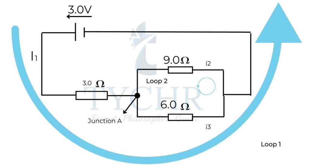
Applying Kirchhoff’s first law at junction 1, 𝐼1 = 𝐼2 + 𝐼3.
Applying Kirchhoff’s second law for loop 1, 3 = 3𝐼1 + 9𝐼2
Applying Kirchhoff’s law for loop 2, 6𝐼3 = 9𝐼2
Solving the above 3 equations, we get 𝐼1 = 0.45𝐴 𝐼2 = 0.18𝐴 𝐼3 = 0.27A.
Electric cells
Cells act as storage devices of electrical energy. They drive electric current in a single direction when connected in a circuit and produce electric current and develop pd between the terminals.
Primary and secondary cells:
Primary cells are consumed completely after a single use and cannot be used multiple times. Leclanche cell is an example of primary cell.
Secondary cells can be charged using electrical energy when consumed multiple times. Lead-acid accumulator cell is a secondary cell.
Capacity:
The capacity of a cell is the ability of the cell to store charge. It is represented in terms of Ah. 1Ah is the charge that can support a current of 1A for 1 hour.
E.g.: The capacity of a cell is 1400mAh. Calculate the time for which it can supply a current of 1.8mA.
Answer. Cell capacity = current × time.
So, Time = Cell Capacity / Current
𝑡𝑖𝑚𝑒 = 1400/1.8 = 780 ℎ𝑜𝑢𝑟s
Discharging cells:
The discharge of a cell typically looks like the graph shown below.
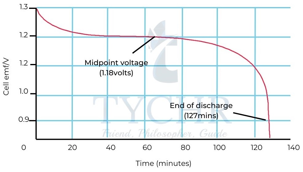
The important features of this graph are:
- The initial emf is greater than the rated emf, but drops rapidly to the rated value.
- Most of the time, the emf remains around the rated emf but there is a slow decline in emf of the cell.
- At the end of life of a cell, the emf rapidly drops to a very low level. When the current is switched off, the emf of the battery may reach the rated value but falls quickly when started to discharge.
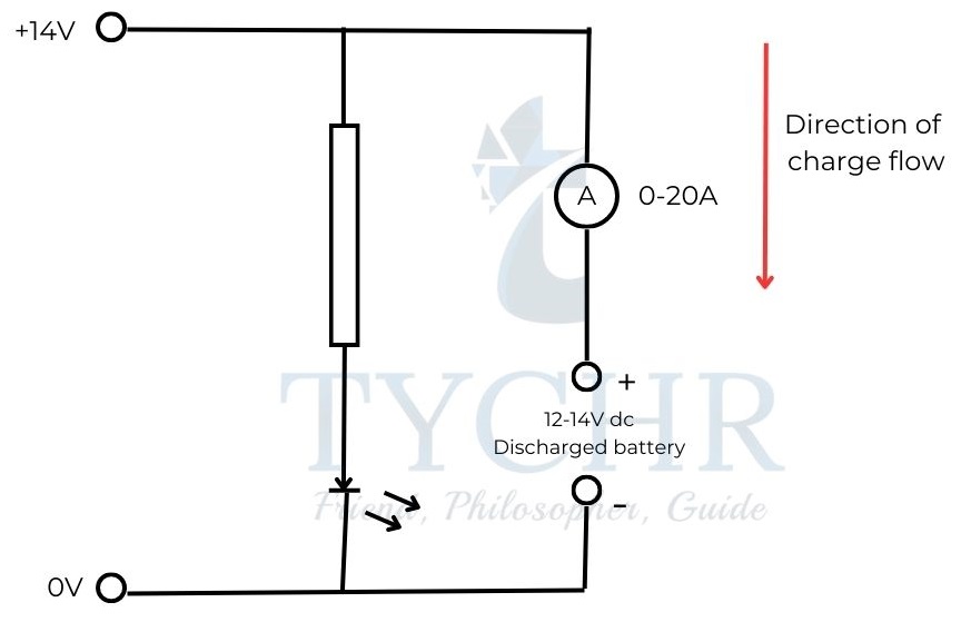
Charging a secondary cell:
A secondary cell can be charged by connecting an external current source of pd higher than that of highest pd that the cell can exhibit.
A sample circuit to charge a secondary cell is given.
Internal resistance and emf of a cell:
Cells show some resistance called internal resistance.
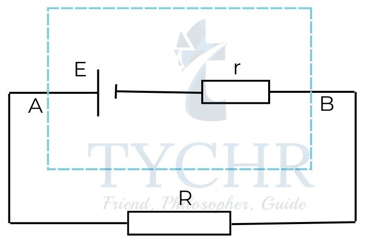
Inside the dotted box, an ideal cell along with a resistor is shown. Together they make up a real cell with r being the internal resistance of the cell.
When a current I flows through the battery, the pd across the terminals of the battery is . When the current I flowing through the battery is zero, the pd across the terminals of the battery is equal to . This is generally stated as the emf of cell.
Power supplied by a cell connected in a circuit to a resistor R is![]() This power is maximum when r=R – the internal resistance of the battery is equal to the external resistance in the circuit.
This power is maximum when r=R – the internal resistance of the battery is equal to the external resistance in the circuit.
E.g.: The emf of a cell is 6.0V and the internal resistance is 2.5Ω. The battery is connected to a resistor of resistance 7.5Ω. Find
a) the current in the cell
b) the terminal pd of the battery.
c) the energy lost in the cell when the current flows for 10s.
Answer.
a) The current in the cell is
𝐼 =𝜖/(𝑅 + 𝑟)=6/(2.5 + 7.5) = 0.6𝐴
b) The terminal pd of the battery is
𝜖 − 𝐼𝑟 = 6 − 0.6(2.5) = 4.5𝑉
c) In 10 s, 6 C flows through the cell and the energy lost in the cell is 1.5 J C-1. The energy lost is 9.0 J.
Wheatstone bridge:
The arrangement of Wheatstone bridge is as shown:
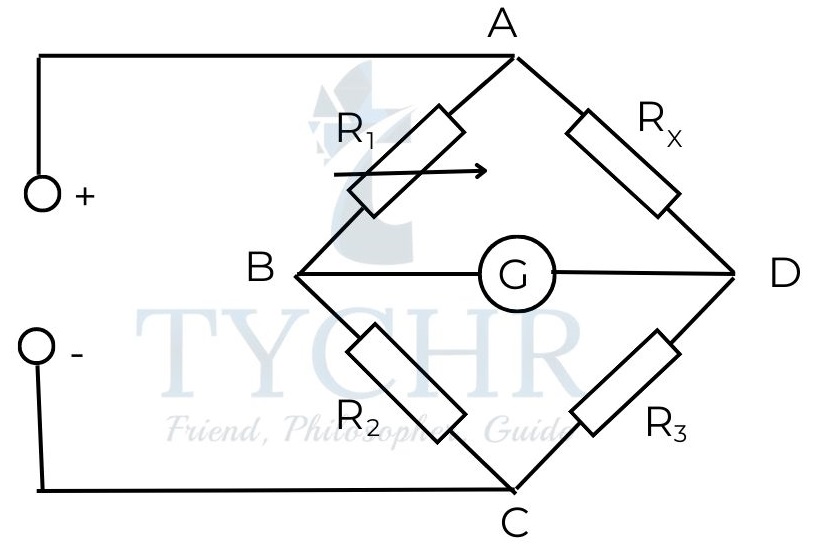
The resistance RX is unknown and can be found using a Wheatstone bridge. The resistance R1 is adjusted such that the reading shown by G is zero. Then the resistance RX is given by
𝑅𝑋 =𝑅1𝑅3/𝑅2
Magnetic effects of electric current
Magnetic field lines are very similar to electric field lines and exhibit properties similar to an electric dipole (two opposite equal charges separated by some distance) as magnetic monopoles are not found to exist in nature.
Magnetic field due to current in conductors:
Magnetic field is produced by moving charges – magnetic field exists if there is an electric current.
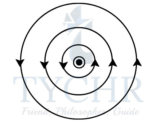
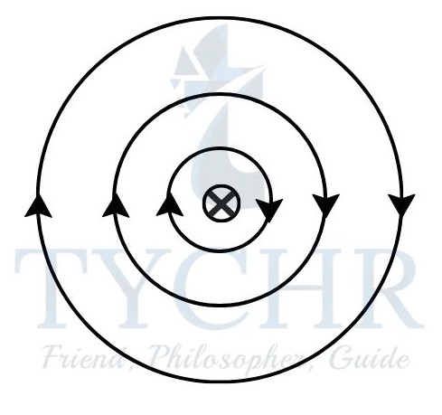
Magnetic field due to a straight wire of infinite length:
The magnetic field is a series of concentric circles around the wire. The direction of the field is given by right-hand corkscrew rule.
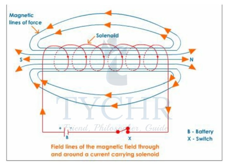
Magnetic field due to a solenoid:
Magnetic field inside an infinitely long solenoid is a straight line whose direction is given by right-hand corkscrew rule.
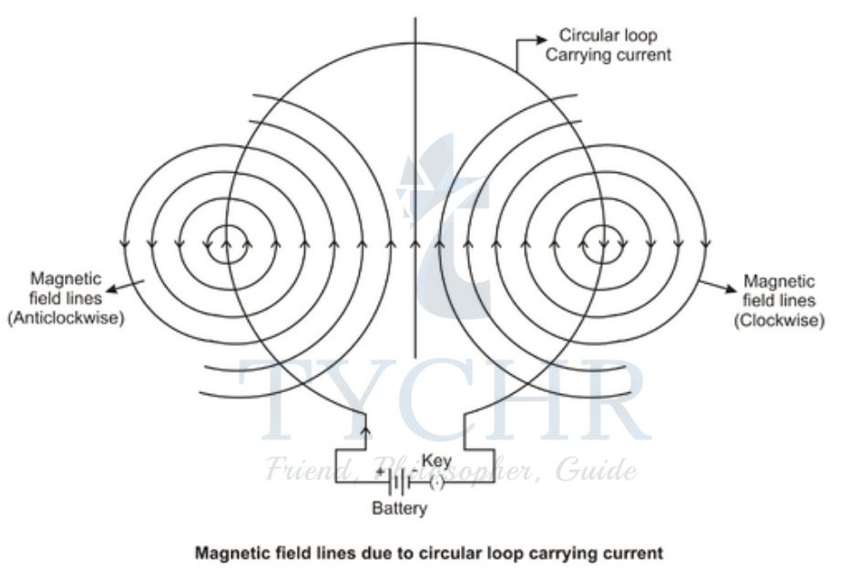
Magnetic field due to a circular wire:
A circular current carrying wire functions just like a bar magnet. Its direction is given by right-hand corkscrew rule.
Forces due to magnetic field:
Consider two straight parallel long wires carrying current. They are attracted to each other if the current in both the wires flows in same direction and repel if the current is in opposite direction.
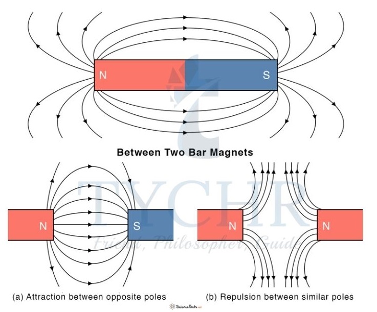
In the first case, the field loops combine to give loops over both the wires. This is similar to magnets when a south pole is brought near a north pole.
Force between a magnet and a wire:
Consider a uniform magnetic field formed and a wire as shown.
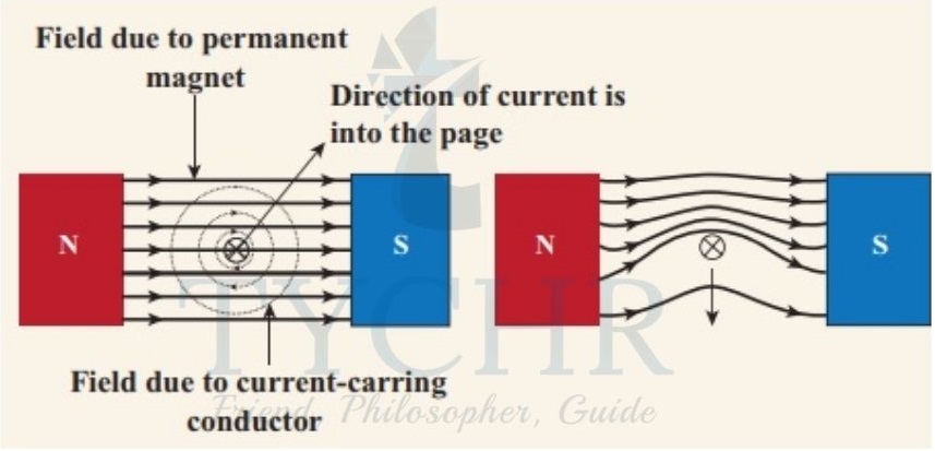
This can be explained by the same principle used for finding force between two wires. The wire experiences force in the direction where the field lines cancel out.
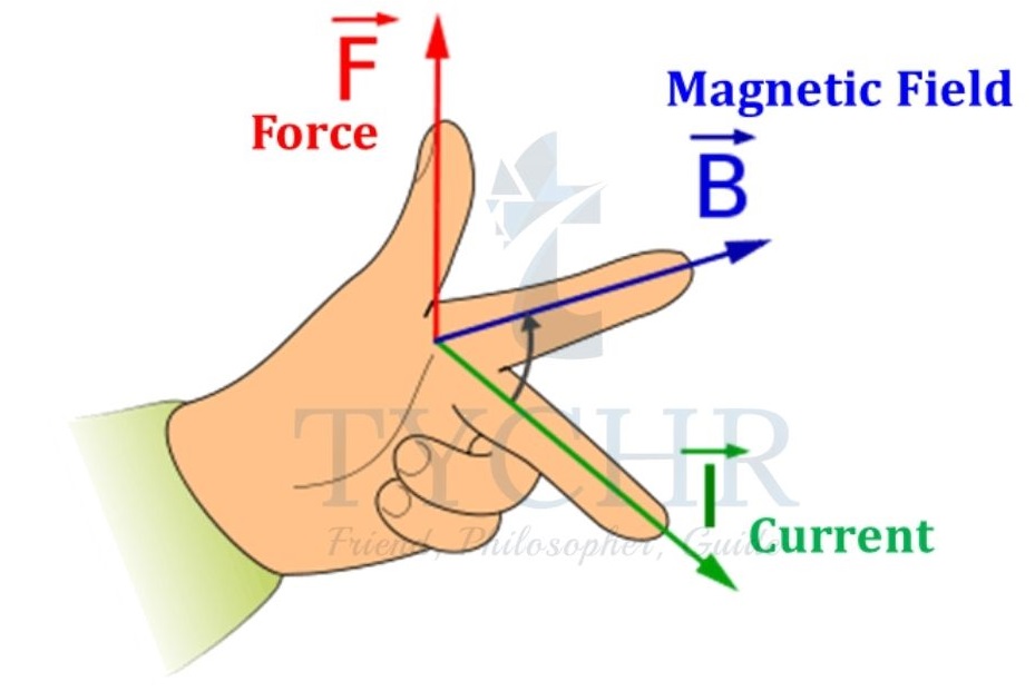
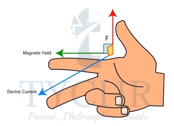
Fleming’s left-hand rule:
This is used to find the direction of force on a wire placed in a magnetic field.
Magnitude of magnetic force:
The magnetic field strength of a field is given by
𝐵 = 𝐹/𝐼L
Here, F is the force experienced by the wire,
I is the current in the wire and L is the length of wire.
This applies to the following arrangement
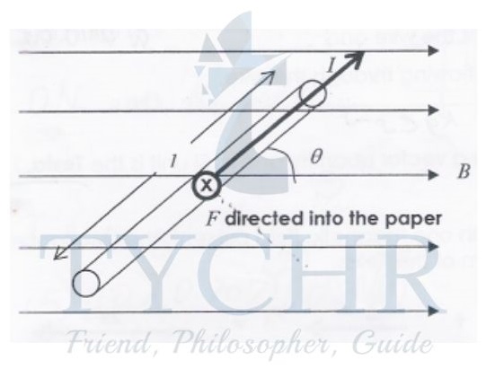
If the wire is aligned at an angle(𝜃) to the field, then the force experienced by the wire is 𝐹 = 𝐵𝑄𝑣𝑠𝑖𝑛𝜃.
If a charge (Q) moves with a velocity (v) in the same way, the force experienced by the charge is 𝐹 = 𝐵𝑄𝑣𝑠𝑖𝑛𝜃.
The direction of force is given by Fleming left hand rule.
Charges in fields:
Consider a charge q entering a magnetic field B with a velocity v perpendicular to the field.
The force experienced by the charge is Bqv perpendicular to the field. This acts as a centripetal force and hence the charge moves in a circle of radius 𝑚𝑣/𝐵q. If the velocity makes an angle with the magnetic field, then the motion is a helix with the radius of circle being 𝑚𝑣𝑠𝑖𝑛𝜃/𝐵𝑞.
Consider a particle (m,q) entering a magnetic field B and an electric field E with a velocity v. The electric, magnetic field and velocity vectors are perpendicular to each other. Then the particle moves in a straight line if the magnetic and electric forces cancel each other. This gives the velocity to be 𝑣 =𝐸/𝐵. Such a field allows particles of speed v to only exit the field and such an arrangement is called velocity selector.
Electromagnetic induction
Conductor moving in a magnetic field:
If a conductor moves in a magnetic field, the (free) charges in the conductor experience force. This drives the charges in the conductor and hence an emf is generated. The current generated in this form is called induced current and emf is called induced emf.
For a straight wire of length L moving in a magnetic field B such that its velocity V is perpendicular to the field, the induced emf generated is 𝜖 = 𝐵𝐿V.
The direction of emf can be found using the diagram below.
Faraday’s law:
The magnetic flux of a field across a cross-section is ∫ 𝐵 𝑐𝑜𝑠𝜃 𝑑𝐴. 𝜃 is the angle made by the area element with the magnetic field.
Faraday’s law is as follows:
The induced emf is equal to the rate of change of magnetic flux.
Lenz’s law:
The direction of induced emf is such that it opposes the change in flux.
Combining these two laws gives
𝜖 = −(Δ𝜙/Δ𝑡)
Power generation and transmission
Generator:
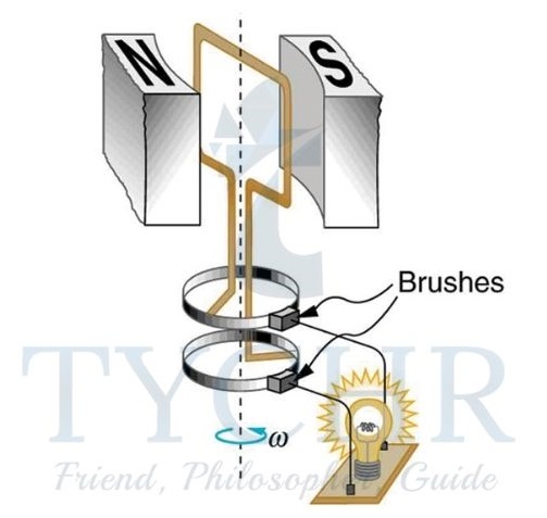
Consider the setup shown,
A coil made of a conducting material is kept in a uniform magnetic field. When the coil is rotated by an external source, the flux enclosed in the coil changes. So, there will be an emf induced in the coil. If the rotation of coil is uniform with an angular frequency , then the emf induced is given by 𝜖 = 𝜖0𝑠𝑖𝑛𝜔𝑡
𝜖0 is the maximum value of emf induced and is equal to BAN𝜔.
This is a source of alternating current.
Power in an AC circuit:
In an AC circuit, rms values of voltage and current have to be taken for calculation of power dissipated or generated.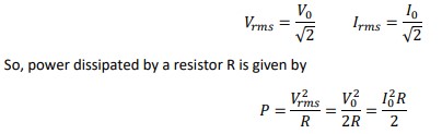
Transformer:
A transformer consists of two coils wounded around a single core. A transformer is used to increase or decrease the pd at which the power is transmitted.
Ideally, the power transmitted does not change.
𝑉𝑆𝐼𝑆 = 𝑉𝑃𝐼𝑃
S represents secondary and P represents primary coils.
The ratio of pds equals the ratio of turns.
𝑉𝑆/𝑉𝑃 = 𝑁𝑆/𝑁𝑃
Rectification:
Rectification is the process of converting AC to DC. This is done by using diodes which are semiconductors doped on one side as P-type and the other as N-type.
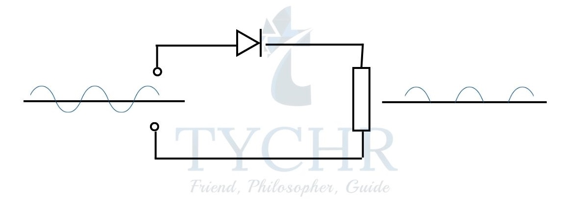
Half wave rectification:
Half wave rectification can be achieved with a single diode as shown.
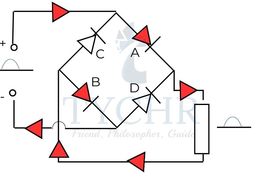
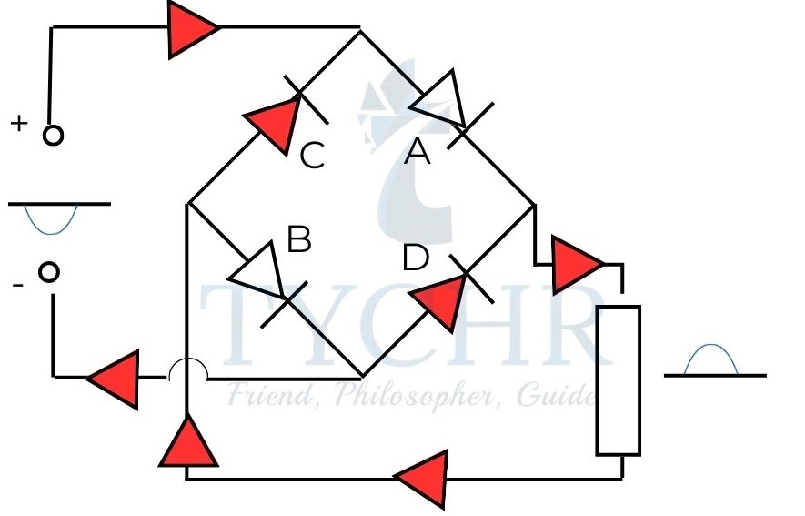
Full wave rectification:
Full wave rectification involves a bridge of rectifiers as shown.