Introduction
Terms related to image formation:
Real and virtual image: If the light rays meet at a point after being reflected or refracted, then the image is real. If they don’t, the light rays are extended backwards and a virtual image is formed at the point of intersection.
Pole (P): The geometric centre of the reflecting or refracting surface is called pole.
Centre of curvature: The centre of the sphere that forms a part of the reflecting or refracting surface.
Principal axis: The line passing through the pole and centre of curvature is the principal axis.
Converging and diverging mirrors: Concave mirrors are converging mirrors and convex mirrors are diverging mirrors.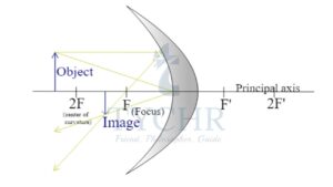
When the object is at infinity, the rays seem to be coming parallel to principal axis. The point at which image is formed in this configuration is called focus and the distance from pole to focus is called focal length.
Image formation:
The predictable rays that are used in image formation are:
- Passing through focus and after reflection travels parallel to the principal axis.
- Passing through the centre of curvature and retracing its path after reflection.
- Travelling parallel to the principal axis and after reflection passes through focus.
A convex mirror always forms virtual images irrespective of the position of objects. A concave mirror forms real images if the object is farther than the focal point and virtual image otherwise.
The mirror formula:
1/𝑓 = (1/𝑢)+(1/v)
Here f is the focal length, u is the object distance and v is the image distance.
All distances are measured from poles. Distances measured in the direction of rays from objects are positive.
Magnification: The ratio of the height of an image to that of an object.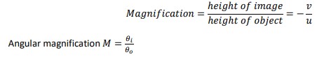
Aberrations in a mirror:
The image formation in above cases is due to rays from object that are close to principal axis. Also, the mirror is considered to be spherical. In real life, spherical mirrors form images along the caustic curve. To minimize these errors, parabolic mirrors are to be used.
E.g.: Construct a ray diagram for a concave mirror when:
i) Object is between F and C
ii) Object is at C
iii) Object is at F
iv) Object is between F and P
Answer.
i)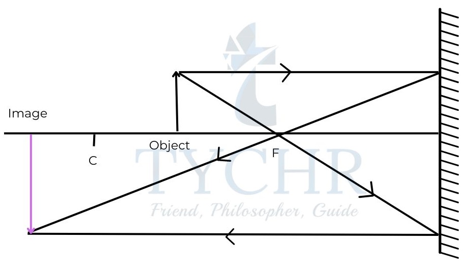
ii)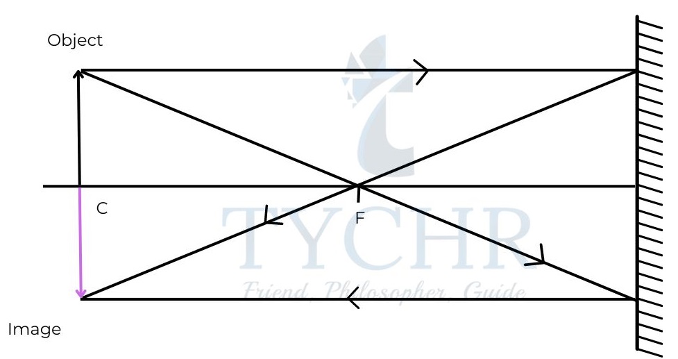
iii)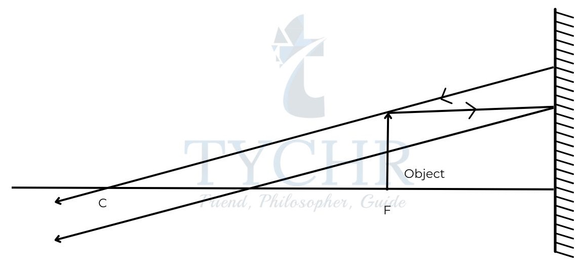
iv)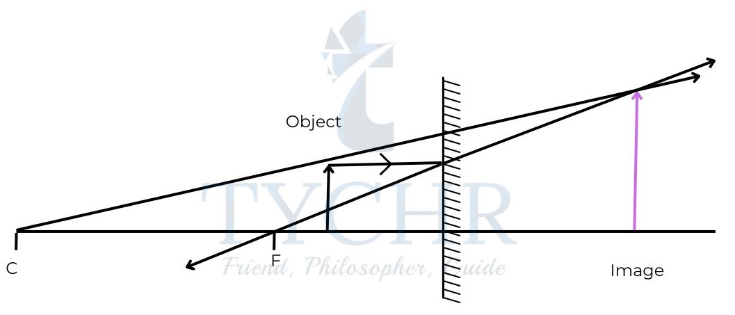
E.g.: Construct a ray diagram for a convex mirror when the object is between the pole of the mirror and focal length.
Answer.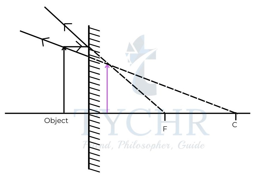
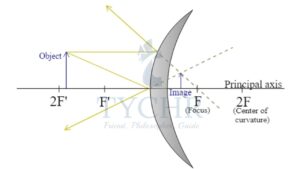
Converging and diverging thin lenses:
Double convex lenses are converging lenses and double concave are diverging.
Terms and image formation are similar to those of mirrors.
The predictable rays used for image formation are also similar.
The lens equation for determining image distance is (1/𝑢) + (1/𝑣) = 1/f
Real object and image distances are positive and virtual object and image distances are negative.
The power of a lens is the inverse of focal length.
𝑃(𝑖𝑛 𝑑𝑖𝑜𝑝𝑡𝑟𝑒) = (1/ 𝑓(𝑖𝑛 𝑚𝑒𝑡𝑒𝑟𝑠))
Magnification is 𝑚 = ℎ𝑒𝑖𝑔ℎ𝑡 𝑜𝑓 𝑖𝑚𝑎𝑔𝑒/ℎ𝑒𝑖𝑔ℎ𝑡 𝑜𝑓 𝑜𝑏𝑗𝑒𝑐𝑡 = 𝑣 / 𝑢
Angular magnification 𝑀 = 𝜃𝑖 / 𝜃𝑜
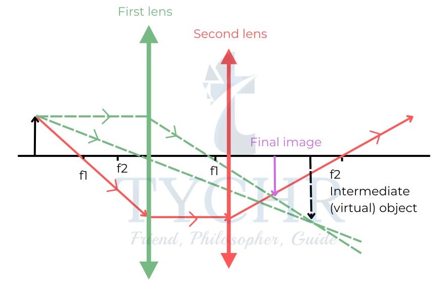
E.g.: a) A converging lens of focal length +15 cm is 25 cm from an object. Calculate the position of the image.
b) Another converging lens also of focal length +25 cm is placed 18 cm from the lens on the image side. Calculate the new position of the image.
Answer.
a) 1/𝑣 = (1 /𝑓) − (1/𝑢) = (1/15) − (1/25); 𝑣 = 37.5cm
b) The new u is 37.5 18 = 19.5 cm from the lens. This is a virtual object for the second lens and so will have a negative sign in the lens equation.
1/𝑣 = (1/25) − (1/(−19.5)) ; 𝑣 = +11𝑐𝑚
The image is formed 11cm from the second lens.
The ray diagram is constructed below.
Magnifying lens:
The least distance of distinct vision (D) of the eye is 25cm. Magnifying lens can be used to reduce strain on the eye.
The lens is held close to the eye and the position of the object can be varied between 2 configurations.
When the object is held at focus, the image forms at infinity making the eye most relaxed.
The angular magnification in this configuration is 𝑀 = 𝐷/𝑓.
When the object is held between focus and pole of the lens, the angular magnification is : 𝑀 = 1 + (𝐷/𝑓)
Aberrations:
Chromatic aberrations:
The refractive index is different for different wavelengths of light and hence is the focal length of a lens. So, the light rays of different wavelengths converge at different points causing formation of colour fringes. The best place to view the image is at the point of convergence of green light. This point is called circle of least confusion. A way to correct chromatic aberrations is to use a doublet lens (converging and a diverging lens).
Spherical lens:
The rays farther from the principal axis are converged closer to the lens than those near the axis. To reduce this, an obstacle with an aperture can be placed to limit the outer rays trading off brightness of image.
Imaging instrumentation
Optical compound microscope:
The lens closer to the object is called objective and that to eye is called eyepiece lens. The focal length of objective 𝑓0, is very small and forms a real, magnified image between pole and focus of eyepiece, which forms a magnified virtual image of the object.
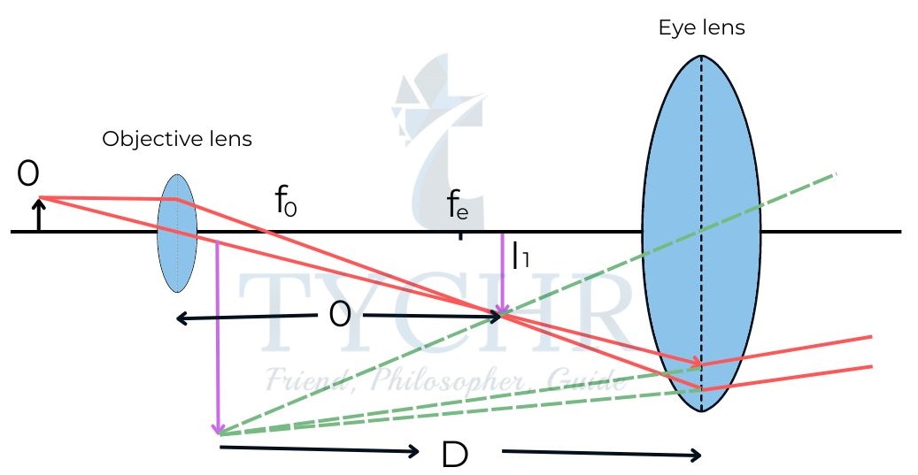
L is the distance between objective and eyepiece.
The final image formed should not be closer to eye than D.
The angular magnification of this microscope is 𝐷𝐿/(𝑓0𝑓𝑒) .
Astronomical refracting telescopes:
In these devices, the focal length of the object is large and that of the eyepiece is small. The object at infinity forms an image at the focus of the object which coincides with the focus of the eyepiece.
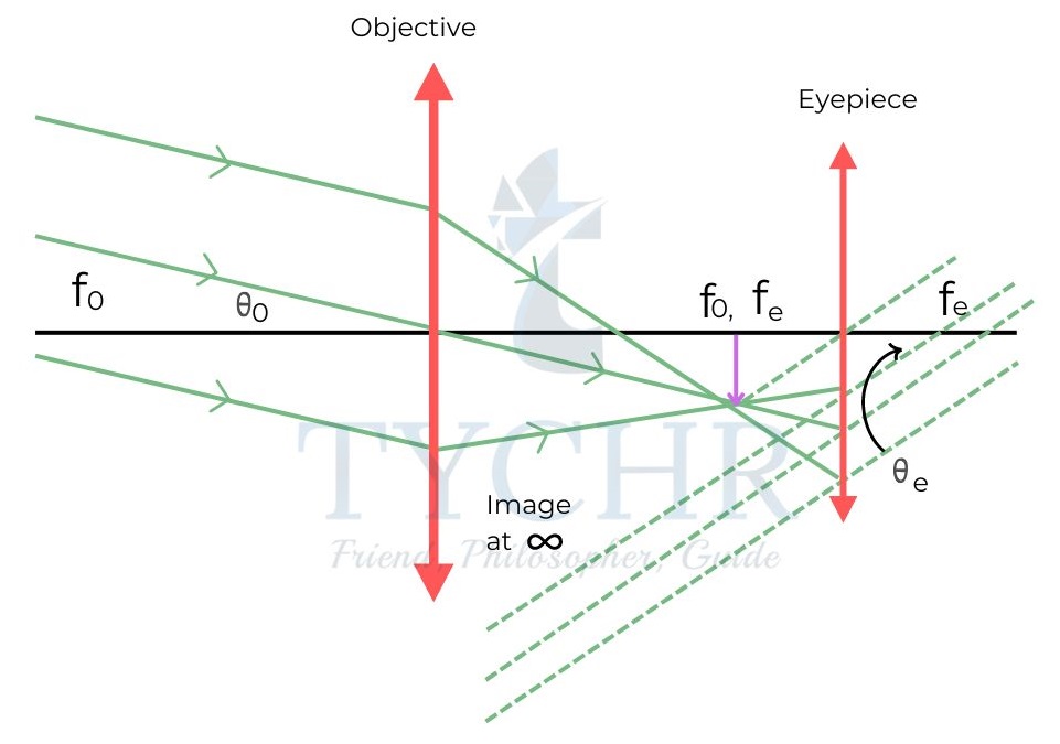
The angular magnification is 𝑀 = 𝜃𝑜/𝜃𝑒 = 𝑓𝑜/𝑓e.
E.g.: An astronomical telescope in normal adjustment has an objective focal length of 150 cm and an eyepiece focal length of 5.0 cm. Calculate:
a) the angular magnification of the telescope
b) the overall length of the telescope.
Answer.
a) 𝑀 = 𝑓𝑜/𝑓e = 150 /5 = 30
b) Overall length𝑓𝑜 + 𝑓𝑒 = 1.55m
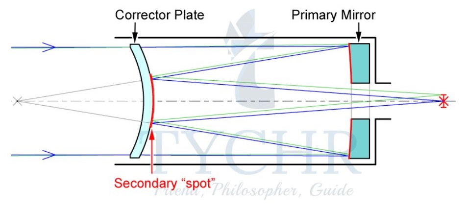
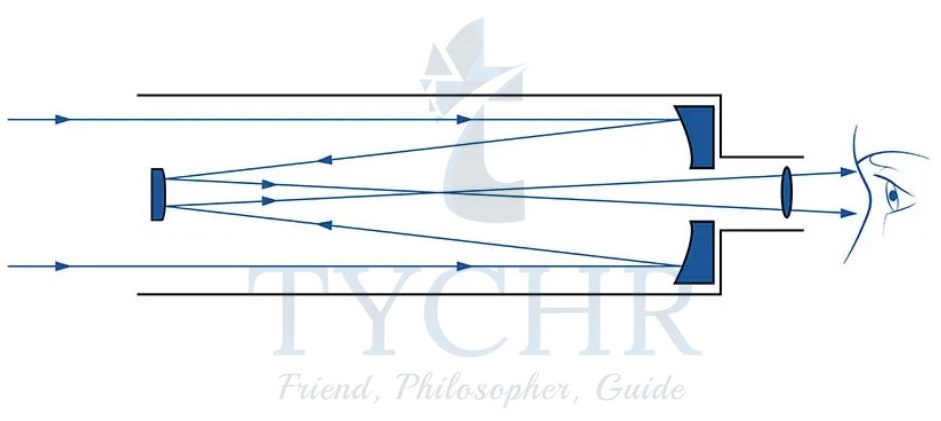
Astronomical reflecting telescopes:
Large parabolic mirrors are used to focus light from distant objects. The image is formed at the focus of the mirror. The angular resolution of a spherical mirror is 𝑠𝑖𝑛𝜃 = 1.22𝜆 / 𝑑. Here, d is the diameter of mirror. So, larger diameter means better resolution. The main advantage of reflecting telescopes is the absence of chromatic aberrations.
The image formed at the focus can be transferred to the outside using various arrangements. Two of them are Newtonian and Cassegrain mountings.
Other telescopes:
Radio telescopes: These are used to focus radio waves. These telescopes need to have large diameters to compensate the loss in resolution due to large wavelengths, usually of the order of hundreds of meters.
Interferometer telescopes: These uses multiple telescopes with an effective baseline B to give a resolution 𝜆/𝐵.The individual telescopes are steerable. The individual signals are combined using a computer. Another method is to use telescopes in different places to give a baseline as big as the planet itself.
Earth and satellite borne telescopes: Stars and other astronomical objects are difficult to observe due to absorption by atmosphere and increasing electromagnetic radiation. So, satellite mounted telescopes are available for viewing certain sections of the sky.
Fibre optics
Fibre optics use the principle of total internal reflection for transmission of information through electromagnetic signals. They are mainly used because of their advantages in security, compactness and transmission without loss.
The types of optical fibres used are
Mark Step index: The change in refractive index between core (inner and optically denser part) and cladding (outer and optically rarer part) is abrupt.
Graded-index: The change in refractive index is gradual.
Single-mode: The diameter is only a few times the wavelength of the light used and involve different principles.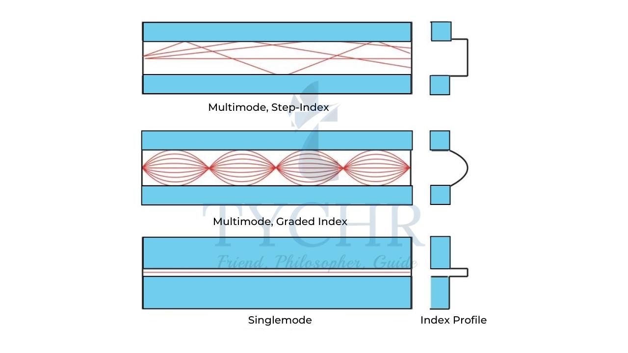
Attenuation and dispersion:
The pulse passing through the fibre suffers attenuation – loss of power and dispersion – spreading out of pulse. The device which amplifies and restores the shape of the output pulse is called repeater. Attenuation is measured in decibels.
If the input signal is 𝐼0 and output signal is 𝐼,
𝐴𝑡𝑡𝑒𝑛𝑢𝑎𝑡𝑖𝑜𝑛(𝐼𝑛 𝑑𝑒𝑐𝑖𝑏𝑒𝑙𝑠) = 10 log(𝐼/𝐼0)
The main causes of attenuation are absorption (infrared waves are greatly absorbed by optical fibres) and scattering (95% of attenuation).
Dispersion is due to material dispersion and waveguide dispersion. Material dispersion is due to different wavelengths used in transmission and reducing material dispersion means to restrict the range of wavelengths transmitted. Waveguide dispersion is due to different times taken by waves along different paths. One way to reduce this is to use graded index fibres.
Imaging the body
X-ray images in medicine:
X-ray imaging in medicine is based on the difference in X-ray attenuation of different parts of the body. The X-ray photons interact through coherent scattering, photoelectric effect, Compton scattering and Pair production.
The intensity of the beam decreases with distance when traveling through a material. This is given by: 𝐼 = 𝐼0𝑒−𝜇1𝑥
I is the intensity of the attenuated beam and I0 is the intensity of the incident beam. 𝜇1 is the linear absorption coefficient.
The intensity of attenuated beam can also be expressed in terms of mass absorption coefficient (𝜇𝑚) and density (𝜌) as:
𝐼 = 𝐼0𝑒−𝜇𝑚𝜌𝑥
Half distance is the distance through which the beam has to travel for its intensity to be halved.
𝑥(1/2) = 𝑙𝑛2 / 𝜇1 = 𝑙𝑛2 / 𝜌𝜇m
Hard X-rays are X-rays of wavelength about 0.01nm and soft X-rays are those of about 1nm.
Improving the image:
The following process is involved to develop a sharp image.

To improve the contrast, methods such as injecting iodine intravenously or drinking a solution of barium sulphate are employed.
Computed tomography (CT):
X-rays are incident on the area of patient under investigation and the scattered and transmitted photons are detected by series of rotating X-ray detectors. The X-ray tube and detectors move around the patient’s body after an exposure and this is repeated to get a 360˚ image of the patient to a depth of few tens of millimeters. A computer collects the data from detectors and builds the image.
Ultrasound in medicine:
Ultrasound is generated using piezoelectric materials. The range of frequencies used in medicine is 2 to 20MHz.
Many ways exist to display the scan.
Type-A scan is graphing the reflected signal strength with respect to time.
Type-B scan involves a computer combining multiple scans to form a whole series of A scans.
Acoustic impedance is a measure of how easy it is to transmit the signal through various materials. Acoustic impedance (Z) of a material is 𝑍 = 𝜌𝑐. c is the speed of sound in the material and 𝜌 is the density of the material.
The ratio of reflected to the incident intensity is :
𝐼/𝐼0=(𝑍2 − 𝑍1)2/(𝑍2 + 𝑍1)2
Where Z1 and Z2 are the acoustic impedances of first and second materials respectively.
Advantages:
Non-invasive, quick, inexpensive, no harmful effects and is of particular importance in soft tissues.
Disadvantages:
Image resolution is limited, non-transmission through bone and cannot be used to image lungs and digestive system due to the presence of air.
Magnetic Resonance Imaging (MRI):
Magnetic resonance imaging involves the use of nuclear magnetic resonance for diagnosis of brain and central nervous system.
When hydrogen atoms are exposed to strong magnetic field, the atoms align themselves along the field. When an additional field called Larmor field is added, the atoms get excited to a higher state. When the field is released, electromagnetic signals are released which contain the information regarding proton content in the body. This information can be used to spatially construct the internal organs..
The disadvantages involved in this process are incapability of some people to strong magnetic fields, local heating in tissues due to radio frequency field and claustrophobia in some people due to prolonged stay in confined spaces during MRI.